How Tape Gateway works
Following, you can find an architectural overview of the Tape Gateway solution.
Tape Gateways
Tape Gateway offers a durable, cost-effective solution to archive your data in the Amazon Web Services Cloud. With its virtual tape library (VTL) interface, you use your existing tape-based backup infrastructure to store data on virtual tape cartridges that you create on your Tape Gateway. Each Tape Gateway is preconfigured with a media changer and tape drives. These are available to your existing client backup applications as iSCSI devices. You add tape cartridges as you need to archive your data.
The following diagram provides an overview of Tape Gateway deployment.
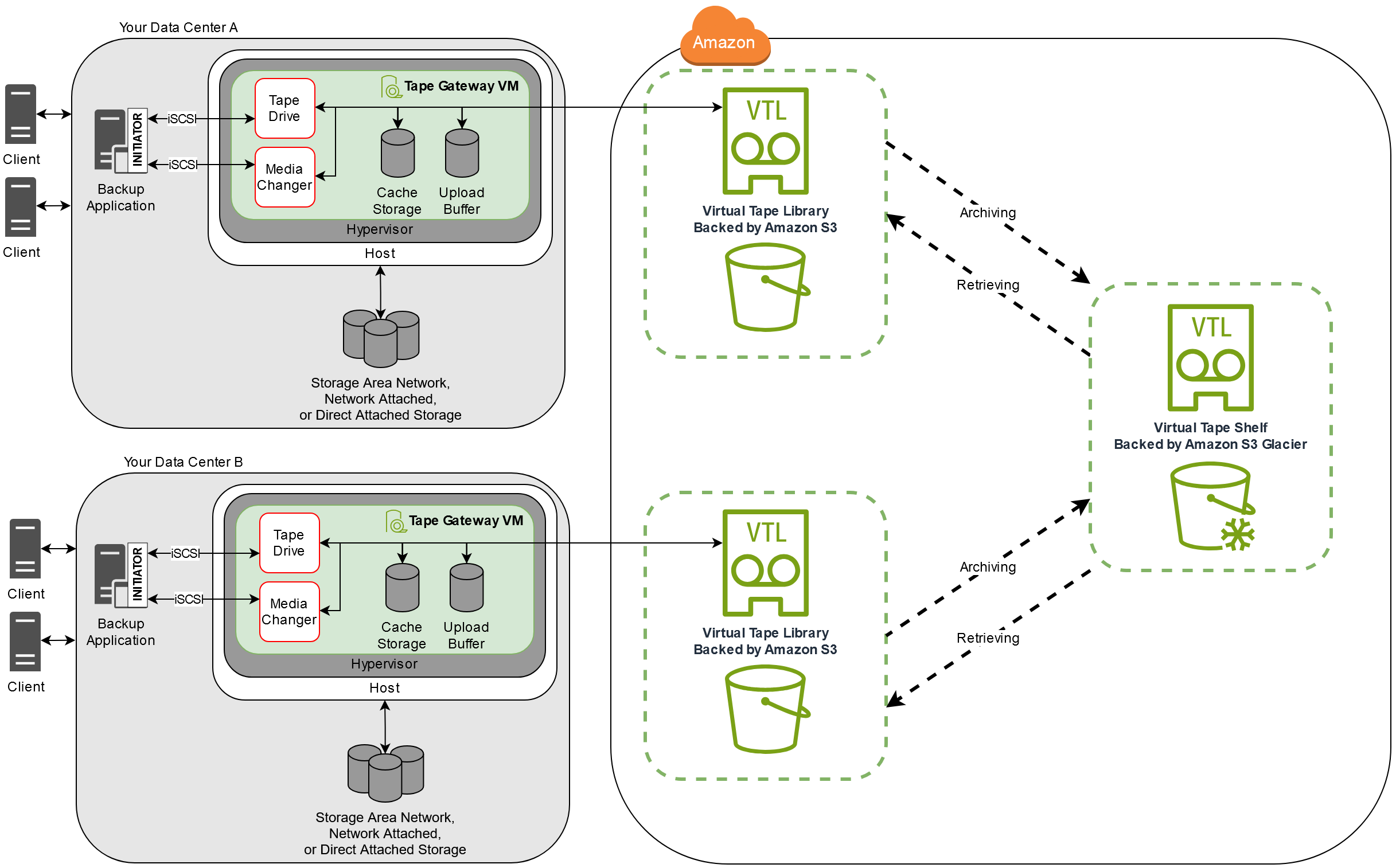
The diagram identifies the following Tape Gateway components:
-
Virtual tape – A virtual tape is like a physical tape cartridge. However, virtual tape data is stored in the Amazon Web Services Cloud. Like physical tapes, virtual tapes can be blank or can have data written on them. You can create virtual tapes either by using the Storage Gateway console or programmatically by using the Storage Gateway API. Each gateway can contain up to 1,500 tapes or up to 1 PiB of total tape data at a time. The size of each virtual tape, which you can configure when you create the tape, is between 100 GiB and 15 TiB.
-
Virtual tape library (VTL) – A VTL is like a physical tape library available on-premises with robotic arms and tape drives. Your VTL includes the collection of stored virtual tapes. Each Tape Gateway comes with one VTL.
The virtual tapes that you create appear in your gateway's VTL. Tapes in the VTL are backed up by Amazon S3. As your backup software writes data to the gateway, the gateway stores data locally and then asynchronously uploads it to virtual tapes in your VTL—that is, Amazon S3.
-
Tape drive – A VTL tape drive is analogous to a physical tape drive that can perform I/O and seek operations on a tape. Each VTL comes with a set of 10 tape drives, which are available to your backup application as iSCSI devices.
-
Media changer – A VTL media changer is analogous to a robot that moves tapes around in a physical tape library's storage slots and tape drives. Each VTL comes with one media changer, which is available to your backup application as an iSCSI device.
-
-
Archive – Archive is analogous to an offsite tape holding facility. You can archive tapes from your gateway's VTL to the archive. If needed, you can retrieve tapes from the archive back to your gateway's VTL.
-
Archiving tapes – When your backup software ejects a tape, your gateway moves the tape to the archive for long-term storage. The archive is located in the Amazon Region in which you activated the gateway. Tapes in the archive are stored in the virtual tape shelf (VTS). The VTS is backed by S3 Glacier Flexible Retrieval or S3 Glacier Deep Archive, low-cost storage service for data archiving, backup, and long-term data retention.
-
Retrieving tapes – You can't read archived tapes directly. To read an archived tape, you must first retrieve it to your Tape Gateway by using either the Storage Gateway console or the Storage Gateway API.
Important
If you archive a tape in S3 Glacier Flexible Retrieval, you can retrieve the tape typically within 3-5 hours. If you archive the tape in S3 Glacier Deep Archive, you can retrieve it typically within 12 hours.
-
After you deploy and activate a Tape Gateway, you mount the virtual tape drives and media changer on your on-premises application servers as iSCSI devices. You create virtual tapes as needed. Then you use your existing backup software application to write data to the virtual tapes. The media changer loads and unloads the virtual tapes into the virtual tape drives for read and write operations.
Allocating local disks for the gateway VM
Your gateway VM needs local disks, which you allocate for the following purposes:
-
Cache storage – The cache storage acts as the durable store for data that is waiting to upload to Amazon S3 from the upload buffer.
If your application reads data from a virtual tape, the gateway saves the data to the cache storage. The gateway stores recently accessed data in the cache storage for low-latency access. If your application requests tape data, the gateway first checks the cache storage for the data before downloading the data from Amazon.
-
Upload buffer – The upload buffer provides a staging area for the gateway before it uploads the data to a virtual tape. The upload buffer is also critical for creating recovery points that you can use to recover tapes from unexpected failures. For more information, see You Need to Recover a Virtual Tape from a Malfunctioning Tape Gateway.
As your backup application writes data to your gateway, the gateway copies data to both the cache storage and the upload buffer. It then acknowledges completion of the write operation to your backup application.
For guidelines on the amount of disk space to allocate for the cache storage and upload buffer, see Deciding the amount of local disk storage.