How Amazon Transit Gateway works
In Amazon Transit Gateway, a transit gateway acts as a Regional virtual router for traffic flowing between your virtual private clouds (VPCs) and on-premises networks. A transit gateway scales elastically based on the volume of network traffic. Routing through a transit gateway operates at layer 3, where the packets are sent to a specific next-hop attachment, based on the destination IP addresses.
Topics
Example architecture diagram
The following diagram shows a transit gateway with three VPC attachments. The route table for each of these VPCs includes the local route and routes that send traffic destined for the other two VPCs to the transit gateway.
The following is an example of a default transit gateway route table for the attachments shown in the previous diagram. The CIDR blocks for each VPC propagate to the route table. Therefore, each attachment can route packets to the other two attachments.
| Destination | Target | Route type |
|---|---|---|
VPC A CIDR
|
Attachment for VPC A
|
propagated |
VPC B CIDR
|
Attachment for VPC B
|
propagated |
VPC C CIDR
|
Attachment for VPC C
|
propagated |
Resource attachments
A transit gateway attachment is both a source and a destination of packets. You can attach the following resources to your transit gateway:
-
One or more VPCs. Amazon Transit Gateway deploys an elastic network interface within VPC subnets, which is then used by the transit gateway to route traffic to and from the chosen subnets. You must have at least one subnet for each Availability Zone, which then enables traffic to reach resources in every subnet of that zone. During attachment creation, resources within a particular Availability Zone can reach a transit gateway only if a subnet is enabled within the same zone. If a subnet route table includes a route to the transit gateway, traffic is only forwarded to the transit gateway if the transit gateway has an attachment in the subnet of the same Availability Zone.
-
One or more VPN connections
-
One or more VPN Concentrators
-
One or more Amazon Direct Connect gateways
-
One or more Transit Gateway Connect attachments
-
One or more transit gateway peering connections
Equal Cost Multipath routing
Amazon Transit Gateway supports Equal Cost Multipath (ECMP) routing for most attachments. For a VPN attachment, you can enable or disable ECMP support using the console when creating or modifying a transit gateway. For all other attachment types, the following ECMP restrictions apply:
-
VPC - VPC does not support ECMP since CIDR blocks cannot overlap. For example, you can't attach a VPC with a CIDR 10.1.0.0/16 with a second VPC using the same CIDR to a transit gateway, and then set up routing to load balance the traffic between them.
-
VPN - When the VPN ECMP support option is disabled, a transit gateway uses internal metrics to determine the preferred path in the event of equal prefixes across multiple paths. For more information on enabling or disabling ECMP for a VPN attachment, see Transit gateways in Amazon Transit Gateway.
-
Amazon Transit Gateway Connect - Amazon Transit Gateway Connect attachments automatically support ECMP.
-
Amazon Direct Connect Gateway - Amazon Direct Connect Gateway attachments automatically support ECMP across multiple Direct Connect Gateway attachments when the network prefix, prefix length, and AS_PATH are exactly the same.
-
Transit gateway peering - Transit gateway peering does not support ECMP since it neither supports dynamic routing nor can you configure the same static route against two different targets.
-
VPN Concentrator - VPN Concentrator does not support ECMP.
Note
-
BGP Multipath AS-Path Relax is not supported, so you can't use ECMP over different Autonomous System Numbers (ASNs).
-
ECMP is not supported between different attachment types. For example, you can't enable ECMP between a VPN and a VPC attachment. Instead, transit gateway routes are evaluated and traffic routed accordingly to the evaluated route. For more information, see Route evaluation order.
-
A single Direct Connect gateway supports ECMP across multiple transit virtual interfaces. Therefore, we recommended that you set up and use only a single Direct Connect gateway and to not set up and use multiple gateways to take advantage of ECMP. For more information about Direct Connect gateways and public virtual interfaces, see How do I set up an Active/Active or Active/Passive Direct Connect connection to Amazon from a public virtual interface?
.
Availability Zones
When you attach a VPC to a transit gateway, you must enable one or more Availability Zones to be used by the transit gateway to route traffic to resources in the VPC subnets. To enable each Availability Zone, you specify exactly one subnet. The transit gateway places a network interface in that subnet using one IP address from the subnet. After you enable an Availability Zone by specifying a subnet, traffic can be routed to all subnets in that Availability Zone, not just the one you specified. However, only resources that reside in Availability Zones where there is a transit gateway attachment can reach the transit gateway.
If traffic is sourced from an Availability Zone that the destination attachment is not present in, Amazon Transit Gateway will internally route that traffic to a random Availability Zone where the attachment is present. There is no additional transit gateway charge for this type of cross-Availability Zone traffic.
We recommend that you enable multiple Availability Zones to ensure availability.
Using appliance mode support
If you plan to configure a stateful network appliance in your VPC, you can enable appliance mode support for the VPC attachment in which the appliance is located. This ensures that the transit gateway uses the same Availability Zone for that VPC attachment for the lifetime of a flow of traffic between source and destination. It also allows the transit gateway to send traffic to any Availability Zone in the VPC, as long as there is a subnet association in that zone. For more information, see Example: Appliance in a shared services VPC.
Routing
Your transit gateway routes IPv4 and IPv6 packets between attachments using transit gateway route tables. You can configure these route tables to propagate routes from the route tables for the attached VPCs, VPN connections, and Direct Connect gateways. You can also add static routes to the transit gateway route tables. When a packet comes from one attachment, it is routed to another attachment using the route that matches the destination IP address.
For transit gateway peering attachments, only static routes are supported.
Routing topics
Route tables
Your transit gateway automatically comes with a default route table. By default, this route table is the default association route table and the default propagation route table. If you disable both route propagation and route table association, Amazon does not create a default route table for the transit gateway. However, if either route propagation or route table association is enabled, Amazon then creates a default route table.
You can create additional route tables for your transit gateway. This enables you to isolate subsets of attachments. Each attachment can be associated with one route table. An attachment can propagate its routes to one or more route tables.
You can create a blackhole route in your transit gateway route table that drops traffic that matches the route.
When you attach a VPC to a transit gateway, you must add a route to your subnet route table in order for traffic to route through the transit gateway. For more information, see Routing for a Transit Gateway in the Amazon VPC User Guide.
Route table association
You can associate a transit gateway attachment with a single route table. Each route table can be associated with zero to many attachments and can forward packets to other attachments.
Route propagation
Each attachment comes with routes that can be installed in one or more transit gateway route tables. When an attachment is propagated to a transit gateway route table, these routes are installed in the route table. You can't filter on advertised routes.
For a VPC attachment, the CIDR blocks of the VPC are propagated to the transit gateway route table.
When dynamic routing is used with a VPN attachment, VPN Concentrator attachment or a Direct Connect gateway attachment, you can propagate the routes learned from the on-premises router through BGP to any of the transit gateway route tables.
When dynamic routing is used with a VPN attachment or a VPN Concentrator attachment, the routes in the route table associated with the VPN attachment or VPN Concentrator attachment are advertised to the customer gateway through BGP.
For a Connect attachment, routes in the route table associated with the Connect attachment are advertised to the third-party virtual appliances, such as SD-WAN appliances, running in a VPC through BGP.
For a Direct Connect gateway attachment, allowed prefixes interactions control which routes are advertised to the customer network from Amazon.
When a static route and a propagated route have the same destination, the static route has the higher priority, so the propagated route is not included in the route table. If you remove the static route, the overlapping propagated route is included in the route table.
Routes for peering attachments
You can peer two transit gateways, and route traffic between them. To do this, you create a peering attachment on your transit gateway, and specify the peer transit gateway with which to create the peering connection. You then create a static route in your transit gateway route table to route traffic to the transit gateway peering attachment. Traffic that's routed to the peer transit gateway can then be routed to the VPC and VPN attachments for the peer transit gateway.
For more information, see Example: Peered transit gateways.
Route evaluation order
Transit gateway routes are evaluated in the following order:
-
The most specific route for the destination address.
-
For routes with the same CIDR, but from different attachment types, the route priority is as follows:
-
Static routes (for example, Site-to-Site VPN static routes)
-
Prefix list referenced routes
-
VPC-propagated routes
-
Direct Connect gateway-propagated routes
-
Transit Gateway Connect-propagated routes
-
Site-to-Site VPN over private Direct Connect-propagated routes
-
Site-to-Site VPN-propagated routes
-
Site-to-Site VPN-Concentrator propagated routes
-
Transit Gateway peering-propagated routes (Cloud WAN)
-
Some attachments support route advertisement over BGP. For routes with the same CIDR, and from the same attachment type, the route priority is controlled by BGP attributes:
-
Shorter AS Path length
-
Lower MED value
-
eBGP over iBGP routes are preferred, if the attachment supports it
Important
-
Amazon can't guarantee a consistent route prioritization order for BGP routes with the same CIDR, attachment type, and BGP attributes as listed above.
-
For routes advertised to a transit gateway without MED, Amazon Transit Gateway will assign the following default values:
-
0 for inbound routes advertised on Direct Connect attachments.
-
100 for inbound routes advertised on VPN and Connect attachments.
-
-
Amazon Transit Gateway only shows a preferred route. A backup route will only appear in the transit gateway route table if the previously active route is no longer advertised — for example, if you are advertising the same routes over the Direct Connect gateway and over Site-to-Site VPN. Amazon Transit Gateway will only show the routes received from the Direct Connect gateway route, which is the preferred route. The Site-to-Site VPN, which is the backup route, will only display when the Direct Connect gateway is no longer advertised.
VPC and transit gateway route table differences
Route table evaluation differs between whether you're using a VPC route table or a transit gateway route table.
The following example shows a VPC route table. The VPC local route has the highest priority, followed by the routes that are the most specific. When a static route and a propagated route have the same destination, the static route has a higher priority.
| Destination | Target | Priority |
|---|---|---|
| 10.0.0.0/16 |
local |
1 |
| 192.168.0.0/16 | pcx-12345 | 2 |
| 172.31.0.0/16 | vgw-12345 (static) or tgw-12345 (static) |
2 |
| 172.31.0.0/16 | vgw-12345 (propagated) | 3 |
| 0.0.0.0/0 | igw-12345 | 4 |
The following example shows a transit gateway route table. If you prefer the Amazon Direct Connect gateway attachment to the VPN attachment, use a BGP VPN connection and propagate the routes in the transit gateway route table.
| Destination | Attachment (Target) | Resource type | Route type | Priority |
|---|---|---|---|---|
| 10.0.0.0/16 | tgw-attach-123 | vpc-1234 | VPC | Static or propagated | 1 |
| 192.168.0.0/16 | tgw-attach-789 | vpn-5678 | VPN | Static | 2 |
| 172.31.0.0/16 | tgw-attach-456 | dxgw_id | Amazon Direct Connect gateway | Propagated | 3 |
| 172.31.0.0/16 | tgw-attach-789 | tgw-connect-peer-123 | Connect | Propagated | 4 |
| 172.31.0.0/16 | tgw-attach-789 | vpn-5678 | VPN | Propagated | 5 |
Network function attachments
A network function attachment is a resource that connects a network security function — for example, an Amazon Network Firewall attachment — directly to your transit gateway. It eliminates the need to manually create and manage inspection VPCs.
With a network function attachment:
-
Amazon automatically creates and manages the underlying infrastructure
-
Traffic can be inspected as it flows through your transit gateway
-
Security policies are applied consistently across your network
-
You can direct traffic through the firewall using simple routing rules
-
The attachment works across multiple Availability Zones for high availability
This integration simplifies network security by allowing you to attach firewalls directly to your transit gateway rather than creating complex routing configurations and managing separate endpoints through separate VPCs.
Amazon Network Firewall integration
Amazon Network Firewall integration allows you to connect a firewall in the form of a group of Gateway Load Balancer Endpoints, one per Availability Zone, in a service-managed buffer VPC. A Network Firewall attachment is created with appliance mode automatically enabled. This eliminates the need to explicitly manage inspection VPCs.
With Network Firewall integration, you no longer need to create and manage inspection VPCs for your Network Firewall deployments. Instead of selecting a VPC and subnets when creating your firewall, you directly select the Transit Gateway, and Amazon automatically provisions and manages all the necessary resources behind the scenes. You'll see a new transit gateway network function attachment rather than an individual firewall endpoint.
For cross-account scenarios, the Transit Gateway can be RAM-shared from the Transit Gateway owner to the Network Firewall owner account, allowing either account to manage the firewall attachment. Once your firewall and attachment are ready, you can simply modify your Transit Gateway route tables to send traffic to the attachment for inspection.
Note
-
Transit Gateway supports only static routing on Network Firewall attachments.
-
Third-party firewalls are not supported.
For more information about firewalls and attachments see Transit gateway network function attachments.
Example transit gateway scenarios
The following are common use cases for transit gateways. Your transit gateways are not limited to these use cases.
Examples
You can configure your transit gateway as a centralized router that connects all of your VPCs, Amazon Direct Connect, and Site-to-Site VPN connections. In this scenario, all attachments are associated with the transit gateway default route table and propagate to the transit gateway default route table. Therefore, all attachments can route packets to each other, with the transit gateway serving as a simple layer 3 IP router.
Overview
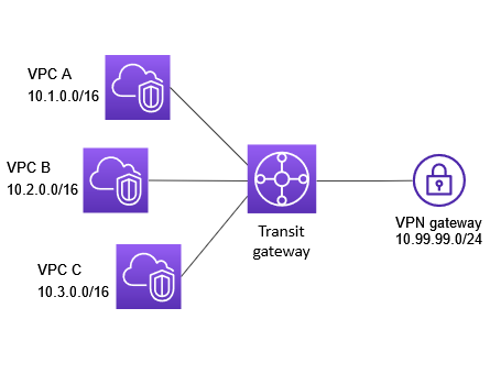
The following diagram shows the key components of the configuration for this scenario. In this scenario, there are three VPC attachments and one Site-to-Site VPN attachment to the transit gateway. Packets from the subnets in VPC A, VPC B, and VPC C that are destined for a subnet in another VPC or for the VPN connection first route through the transit gateway.
Resources
Create the following resources for this scenario:
-
Three VPCs. For more information, see Create a VPC in the Amazon VPC User Guide.
-
A transit gateway. For more information, see Create a transit gateway in Amazon Transit Gateway.
-
Three VPC attachments on the transit gateway. For more information, see Create a VPC attachment in Amazon Transit Gateway.
-
A Site-to-Site VPN attachment on the transit gateway. The CIDR blocks for each VPC propagate to the transit gateway route table. When the VPN connection is up, the BGP session is established and the Site-to-Site VPN CIDR propagates to the transit gateway route table and the VPC CIDRs are added to the customer gateway BGP table. For more information, see Create a transit gateway attachment to a VPN in Amazon Transit Gateway.
Ensure that you review the requirements for your customer gateway device in the Amazon Site-to-Site VPN User Guide.
Routing
Each VPC has a route table and there is a route table for the transit gateway.
VPC route tables
Each VPC has a route table with 2 entries. The first entry is the default entry for local IPv4 routing in the VPC; this entry enables the instances in this VPC to communicate with each other. The second entry routes all other IPv4 subnet traffic to the transit gateway. The following table shows the VPC A routes.
| Destination | Target |
|---|---|
|
10.1.0.0/16 |
local |
|
0.0.0.0/0 |
tgw-id |
Transit gateway route table
The following is an example of a default route table for the attachments shown in the previous diagram, with route propagation enabled.
| Destination | Target | Route type |
|---|---|---|
|
10.1.0.0/16 |
|
propagated |
|
10.2.0.0/16 |
|
propagated |
|
10.3.0.0/16 |
|
propagated |
|
10.99.99.0/24 |
Attachment for VPN connection |
propagated |
Customer gateway BGP table
The customer gateway BGP table contains the following VPC CIDRs.
-
10.1.0.0/16
-
10.2.0.0/16
-
10.3.0.0/16
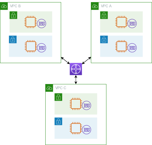
You can configure your transit gateway as multiple isolated routers. This is similar to using multiple transit gateways, but provides more flexibility in cases where the routes and attachments might change. In this scenario, each isolated router has a single route table. All attachments associated with an isolated router propagate and associate with its route table. Attachments associated with one isolated router can route packets to each other, but cannot route packets to or receive packets from the attachments for another isolated router.
Overview
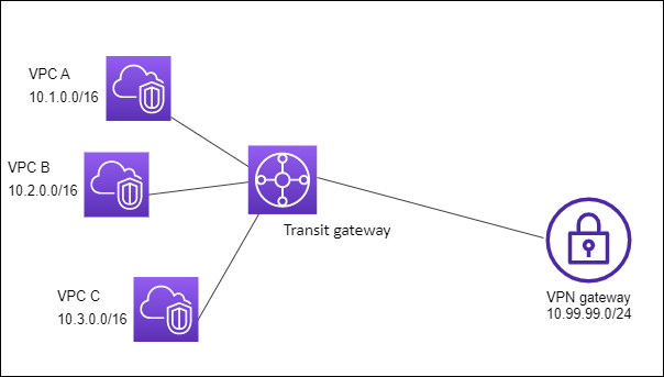
The following diagram shows the key components of the configuration for this scenario. Packets from VPC A, VPC B, and VPC C route to the transit gateway. Packets from the subnets in VPC A, VPC B, and VPC C that have the internet as a destination first route through the transit gateway and then route to the Site-to-Site VPN connection (if the destination is within that network). Packets from one VPC that have a destination of a subnet in another VPC, for example from 10.1.0.0 to 10.2.0.0, route through the transit gateway, where they are blocked because there is no route for them in the transit gateway route table.
Resources
Create the following resources for this scenario:
-
Three VPCs. For more information, see Create a VPC in the Amazon VPC User Guide.
-
A transit gateway. For more information, see Create a transit gateway in Amazon Transit Gateway.
-
Three attachments on the transit gateway for the three VPCs. For more information, see Create a VPC attachment in Amazon Transit Gateway.
-
A Site-to-Site VPN attachment on the transit gateway. For more information, see Create a transit gateway attachment to a VPN in Amazon Transit Gateway. Ensure that you review the requirements for your customer gateway device in the Amazon Site-to-Site VPN User Guide.
When the VPN connection is up, the BGP session is established and the VPN CIDR propagates to the transit gateway route table and the VPC CIDRs are added to the customer gateway BGP table.
Routing
Each VPC has a route table, and the transit gateway has two route tables—one for the VPCs and one for the VPN connection.
VPC A, VPC B, and VPC C route tables
Each VPC has a route table with 2 entries. The first entry is the default entry for local IPv4 routing in the VPC. This entry enables the instances in this VPC to communicate with each other. The second entry routes all other IPv4 subnet traffic to the transit gateway. The following table shows the VPC A routes.
| Destination | Target |
|---|---|
|
10.1.0.0/16 |
local |
| 0.0.0.0/0 |
tgw-id |
Transit gateway route tables
This scenario uses one route table for the VPCs and one route table for the VPN connection.
The VPC attachments are associated with the following route table, which has a propagated route for the VPN attachment.
| Destination | Target | Route type |
|---|---|---|
| 10.99.99.0/24 | Attachment for VPN connection |
propagated |
The VPN attachment is associated with the following route table, which has propagated routes for each of the VPC attachments.
| Destination | Target | Route type |
|---|---|---|
|
10.1.0.0/16 |
|
propagated |
|
10.2.0.0/16 |
|
propagated |
|
10.3.0.0/16 |
|
propagated |
For more information about propagating routes in a transit gateway route table, see Enable route propagation to a transit gateway route table in Amazon Transit Gateway.
Customer gateway BGP table
The customer gateway BGP table contains the following VPC CIDRs.
-
10.1.0.0/16
-
10.2.0.0/16
-
10.3.0.0/16
You can configure your transit gateway as multiple isolated routers that use a shared service. This is similar to using multiple transit gateways, but provides more flexibility in cases where the routes and attachments might change. In this scenario, each isolated router has a single route table. All attachments associated with an isolated router propagate and associate with its route table. Attachments associated with one isolated router can route packets to each other, but cannot route packets to or receive packets from the attachments for another isolated router. Attachments can route packets to or receive packets from the shared services. You can use this scenario when you have groups that need to be isolated, but use a shared service, for example a production system.
Overview
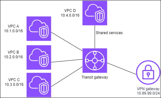
The following diagram shows the key components of the configuration for this scenario. Packets from the subnets in VPC A, VPC B, and VPC C that have the internet as a destination, first route through the transit gateway and then route to the customer gateway for Site-to-Site VPN. Packets from subnets in VPC A, VPC B, or VPC C that have a destination of a subnet in VPC A, VPC B, or VPC C route through the transit gateway, where they are blocked because there is no route for them in the transit gateway route table. Packets from VPC A, VPC B, and VPC C that have VPC D as the destination route through the transit gateway and then to VPC D.
Resources
Create the following resources for this scenario:
-
Four VPCs. For more information, see Create a VPC in the Amazon VPC User Guide.
-
A transit gateway. For more information, see Create a transit gateway.
-
Four attachments on the transit gateway, one per VPC. For more information, see Create a VPC attachment in Amazon Transit Gateway.
-
A Site-to-Site VPN attachment on the transit gateway. For more information, see Create a transit gateway attachment to a VPN in Amazon Transit Gateway.
Ensure that you review the requirements for your customer gateway device in the Amazon Site-to-Site VPN User Guide.
When the VPN connection is up, the BGP session is established and the VPN CIDR propagates to the transit gateway route table and the VPC CIDRs are added to the customer gateway BGP table.
-
Each isolated VPC is associated with the isolated route table and propagated to the shared route table.
-
Each shared services VPC is associated with the shared route table and propagated to both route tables.
Routing
Each VPC has a route table, and the transit gateway has two route tables—one for the VPCs and one for the VPN connection and shared services VPC.
VPC A, VPC B, VPC C, and VPC D route tables
Each VPC has a route table with two entries. The first entry is the default entry for local routing in the VPC; this entry enables the instances in this VPC to communicate with each other. The second entry routes all other IPv4 subnet traffic to the transit gateway.
| Destination | Target |
|---|---|
| 10.1.0.0/16 | local |
| 0.0.0.0/0 | transit gateway ID |
Transit gateway route tables
This scenario uses one route table for the VPCs and one route table for the VPN connection.
The VPC A, B, and C attachments are associated with the following route table, which has a propagated route for the VPN attachment and a propagated route for the attachment for VPC D.
| Destination | Target | Route type |
|---|---|---|
| 10.99.99.0/24 | Attachment for VPN connection |
propagated |
| 10.4.0.0/16 | Attachment for VPC D |
propagated |
The VPN attachment and shared services VPC (VPC D) attachments are associated with the following route table, which has entries that point to each of the VPC attachments. This enables communication to the VPCs from the VPN connection and the shared services VPC.
| Destination | Target | Route type |
|---|---|---|
| 10.1.0.0/16 | Attachment for VPC A |
propagated |
| 10.2.0.0/16 | Attachment for VPC B |
propagated |
| 10.3.0.0/16 | Attachment for VPC C |
propagated |
For more information, see Enable route propagation to a transit gateway route table in Amazon Transit Gateway.
Customer gateway BGP table
The customer gateway BGP table contains the CIDRs for all four VPCs.
You can create a transit gateway peering connection between transit gateways. You can then route traffic between the attachments for each of the transit gateways. In this scenario, VPC and VPN attachments are associated with the transit gateway default route tables, and they propagate to the transit gateway default route tables. Each transit gateway route table has a static route that points to the transit gateway peering attachment.
Overview
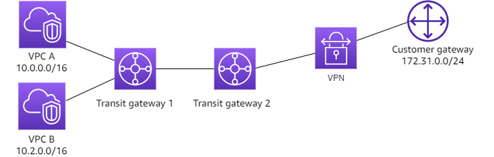
The following diagram shows the key components of the configuration for this scenario. Transit gateway 1 has two VPC attachments, and transit gateway 2 has one Site-to-Site VPN attachment. Packets from the subnets in VPC A and VPC B that have the internet as a destination first route through transit gateway 1, then transit gateway 2, and then route to the VPN connection.
Resources
Create the following resources for this scenario:
-
Two VPCs. For more information, see Create a VPC in the Amazon VPC User Guide.
-
Two transit gateways. They can be in the same Region or in different Regions. For more information, see Create a transit gateway in Amazon Transit Gateway.
-
Two VPC attachments on the first transit gateway. For more information, see Create a VPC attachment in Amazon Transit Gateway.
-
A Site-to-Site VPN attachment on the second transit gateway. For more information, see Create a transit gateway attachment to a VPN in Amazon Transit Gateway. Ensure that you review the requirements for your customer gateway device in the Amazon Site-to-Site VPN User Guide.
-
A transit gateway peering attachment between the two transit gateways. For more information, see Transit gateway peering attachments in Amazon Transit Gateway.
When you create the VPC attachments, the CIDRs for each VPC propagate to the route table for transit gateway 1. When the VPN connection is up, the following actions occur:
-
The BGP session is established
-
The Site-to-Site VPN CIDR propagates to the route table for transit gateway 2
-
The VPC CIDRs are added to the customer gateway BGP table
Routing
Each VPC has a route table and each transit gateway has a route table.
VPC A and VPC B route tables
Each VPC has a route table with 2 entries. The first entry is the default entry for local IPv4 routing in the VPC. This default entry enables the resources in this VPC to communicate with each other. The second entry routes all other IPv4 subnet traffic to the transit gateway. The following table shows the VPC A routes.
| Destination | Target |
|---|---|
|
10.0.0.0/16 |
local |
|
0.0.0.0/0 |
tgw-1-id |
Transit gateway route tables
The following is an example of the default route table for transit gateway 1, with route propagation enabled.
| Destination | Target | Route type |
|---|---|---|
|
10.0.0.0/16 |
|
propagated |
|
10.2.0.0/16 |
|
propagated |
|
0.0.0.0/0 |
Attachment ID for peering connection |
static |
The following is an example of the default route table for transit gateway 2, with route propagation enabled.
| Destination | Target | Route type |
|---|---|---|
|
172.31.0.0/24 |
Attachment ID for VPN connection |
propagated |
|
10.0.0.0/16 |
|
static |
|
10.2.0.0/16 |
Attachment ID for peering connection
|
static |
Customer gateway BGP table
The customer gateway BGP table contains the following VPC CIDRs.
-
10.0.0.0/16
-
10.2.0.0/16
You can configure a transit gateway to route outbound internet traffic from a VPC without an internet gateway to a VPC that contains a NAT gateway and an internet gateway.
Overview
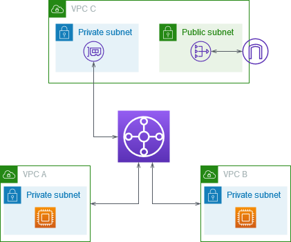
The following diagram shows the key components of the configuration for this scenario. You have applications in VPC A and VPC B that need outbound only internet access. You configure VPC C with a public NAT gateway and an internet gateway, and a private subnet for the VPC attachment. Connect all VPCs to a transit gateway. Configure routing so that outbound internet traffic from VPC A and VPC B traverses the transit gateway to VPC C. The NAT gateway in VPC C routes the traffic to the internet gateway.
Resources
Create the following resources for this scenario:
-
Three VPCs with IP address ranges that are neither identical nor overlap. For more information, see Create a VPC in the Amazon VPC User Guide.
-
VPC A and VPC B each have private subnets with EC2 instances.
-
VPC C has the following:
-
An internet gateway attached to the VPC. For more information, see Create and attach an internet gateway in the Amazon VPC User Guide.
-
A public subnet with a NAT gateway. For more information, see Create a NAT gateway in the Amazon VPC User Guide.
-
A private subnet for the transit gateway attachment. The private subnet should be in the same Availability Zone as the public subnet.
-
-
One transit gateway. For more information, see Create a transit gateway in Amazon Transit Gateway.
-
Three VPC attachments on the transit gateway. The CIDR blocks for each VPC propagate to the transit gateway route table. For more information, see Create a VPC attachment in Amazon Transit Gateway. For VPC C, you must create the attachment using the private subnet. If you create the attachment using the public subnet, the instance traffic is routed to the internet gateway, but the internet gateway drops the traffic because the instances don't have public IP addresses. By placing the attachment in the private subnet, the traffic is routed to the NAT gateway, and the NAT gateway sends the traffic to the internet gateway using its Elastic IP address as the source IP address.
Routing
There are route tables for each VPC and a route table for the transit gateway.
Route tables
Route table for VPC A
The following is an example route table. The first entry enables instances in the VPC to communicate with each other. The second entry routes all other IPv4 subnet traffic to the transit gateway.
| Destination | Target |
|---|---|
|
|
local |
|
0.0.0.0/0 |
|
Route table for VPC B
The following is an example route table. The first entry enables the instances in the VPC to communicate with each other. The second entry routes all other IPv4 subnet traffic to the transit gateway.
| Destination | Target |
|---|---|
|
|
local |
|
0.0.0.0/0 |
|
Route tables for VPC C
Configure the subnet with the NAT gateway as a public subnet by adding a route to the internet gateway. Leave the other subnet as a private subnet.
The following is an example route table for the public subnet. The first entry enables instances in the VPC to communicate with each other. The second and third entries route traffic for VPC A and VPC B to the transit gateway. The remaining entry routes all other IPv4 subnet traffic to the internet gateway.
| Destination | Target |
|---|---|
VPC C CIDR |
local |
VPC A CIDR |
transit-gateway-id |
VPC B CIDR |
transit-gateway-id |
| 0.0.0.0/0 | internet-gateway-id |
The following is an example route table for the private subnet. The first entry enables instances in the VPC to communicate with each other. The second entry routes all other IPv4 subnet traffic to the NAT gateway.
| Destination | Target |
|---|---|
VPC C CIDR |
local |
| 0.0.0.0/0 | nat-gateway-id |
Transit gateway route table
The following is an example of the transit gateway route table. The CIDR blocks for each VPC propagate to the transit gateway route table. The static route sends outbound internet traffic to VPC C. You can optionally prevent inter-VPC communication by adding a blackhole route for each VPC CIDR.
| CIDR | Attachment | Route type |
|---|---|---|
|
|
|
propagated |
|
|
|
propagated |
|
|
|
propagated |
| 0.0.0.0/0 |
|
static |
You can configure an appliance (such as a security appliance) in a shared services VPC. All traffic that's routed between transit gateway attachments is first inspected by the appliance in the shared services VPC. When appliance mode is enabled, a transit gateway selects a single network interface in the appliance VPC, using a flow hash algorithm, to send traffic to for the life of the flow. The transit gateway uses the same network interface for the return traffic. This ensures that bidirectional traffic is routed symmetrically—it's routed through the same Availability Zone in the VPC attachment for the life of the flow. If you have multiple transit gateways in your architecture, each transit gateway maintains its own session affinity, and each transit gateway can select a different network interface.
You must connect exactly one transit gateway to the appliance VPC to guarantee flow stickiness. Connecting multiple transit gateways to a single appliance VPC does not guarantee flow stickiness because the transit gateways do not share flow state information with each other.
Important
-
Traffic in appliance mode is routed correctly as long as the source and destination traffic are coming to a centralized VPC (Inspection VPC) from the same transit gateway attachment. Traffic can drop if the source and destination are on two different transit gateway attachments. Traffic can drop if the centralized VPC receives the traffic from a different gateway — for example, an Internet gateway — and then sends that traffic to the transit gateway attachment after inspection.
-
Enabling appliance mode on an existing attachment might affect that attachment's current route as the attachment can flow through any Availability Zone. When appliance mode is not enabled, traffic is kept to the originating Availability Zone.
Overview
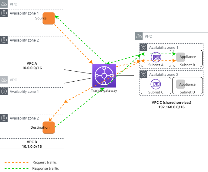
The following diagram shows the key components of the configuration for this scenario. The transit gateway has three VPC attachments. VPC C is a shared services VPC. Traffic between VPC A and VPC B is routed to the transit gateway, then routed to a security appliance in VPC C for inspection before it's routed to the final destination. The appliance is a stateful appliance, therefore both the request and response traffic is inspected. For high availability, there is an appliance in each Availability Zone in VPC C.
You create the following resources for this scenario:
-
Three VPCs. For more information, see Create a VPC in the Amazon VPC User Guide.
-
A transit gateway. For more information, see Create a transit gateway in Amazon Transit Gateway.
-
Three VPC attachments - one for each of the VPCs. For more information, see Create a VPC attachment in Amazon Transit Gateway.
For each VPC attachment, specify a subnet in each Availability Zone. For the shared services VPC, these are the subnets where traffic is routed to the VPC from the transit gateway. In the preceding example, these are subnets A and C.
For the VPC attachment for VPC C, enable appliance mode support so that response traffic is routed to the same Availability Zone in VPC C as the source traffic.
The Amazon VPC console supports appliance mode. You can also use the Amazon VPC API, an Amazon SDK, the Amazon CLI to enable appliance mode, or Amazon CloudFormation. For example, add
--options ApplianceModeSupport=enableto the create-transit-gateway-vpc-attachment or modify-transit-gateway-vpc-attachment command.
Note
Flow stickiness in appliance mode is guaranteed only for source and destination traffic that originate towards the Inspection VPC.
Stateful appliances and appliance mode
If your VPC attachments span multiple Availability Zones and you require traffic between source and destination hosts to be routed through the same appliance for stateful inspection, enable appliance mode support for the VPC attachment in which the appliance is located.
For more information, see Centralized inspection architecture
Behavior when appliance mode is not enabled
When appliance mode is not enabled, a transit gateway attempts to keep traffic routed between VPC attachments in the originating Availability Zone until it reaches its destination. Traffic crosses Availability Zones between attachments only if there is an Availability Zone failure or if there are no subnets associated with a VPC attachment in that Availability Zone.
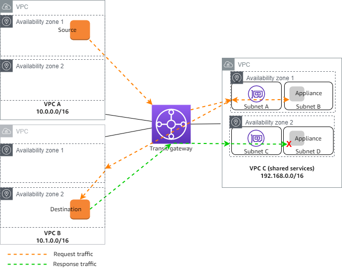
The following diagram shows a traffic flow when appliance mode support is not enabled. The response traffic that originates from Availability Zone 2 in VPC B is routed by the transit gateway to the same Availability Zone in VPC C. The traffic is therefore dropped, because the appliance in Availability Zone 2 is not aware of the original request from the source in VPC A.
Routing
Each VPC has one or more route tables and the transit gateway has two route tables.
VPC route tables
VPC A and VPC B
VPCs A and B have route tables with 2 entries. The first entry is the default entry for local IPv4 routing in the VPC. This default entry enables the resources in this VPC to communicate with each other. The second entry routes all other IPv4 subnet traffic to the transit gateway. The following is the route table for VPC A.
| Destination | Target |
|---|---|
|
10.0.0.0/16 |
local |
|
0.0.0.0/0 |
tgw-id |
VPC C
The shared services VPC (VPC C) has different route tables for each subnet. Subnet A is used by the transit gateway (you specify this subnet when you create the VPC attachment). The route table for subnet A routes all traffic to the appliance in subnet B.
| Destination | Target |
|---|---|
|
192.168.0.0/16 |
local |
|
0.0.0.0/0 |
appliance-eni-id |
The route table for subnet B (which contains the appliance) routes the traffic back to the transit gateway.
| Destination | Target |
|---|---|
|
192.168.0.0/16 |
local |
|
0.0.0.0/0 |
tgw-id |
Transit gateway route tables
This transit gateway uses one route table for VPC A and VPC B, and one route table for the shared services VPC (VPC C).
The VPC A and VPC B attachments are associated with the following route table. The route table routes all traffic to VPC C.
| Destination | Target | Route type |
|---|---|---|
|
0.0.0.0/0 |
|
static |
The VPC C attachment is associated with the following route table. It routes traffic to VPC A and VPC B.
| Destination | Target | Route type |
|---|---|---|
|
10.0.0.0/16 |
|
propagated |
|
10.1.0.0/16 |
|
propagated |